How to draw Vectors in Geogebra
In this post, i will be talking about a few ways to construct vector arrows in Geogebra - an online graphing calculator. I have been using this software for quite some time now. It has greatly helped me to embed visual pictures in my explanations on various topics in 3D geometry where vectors play a significant role.
Here, I will be sharing some of the tools and commands in Geogebra that I have used for constructing vector arrows.
Before proceeding ahead, i am going to make a supposition that a reader is familiar with the basic theory about vectors. So without wasting any time let me get straight to it.
In case you want to practice all the constructions simultaneously along with me, you can click here to open the 2D calculator in the adjacent tab.
Constructing vector arrows from the coordinates of the tip and the tail
As soon as you type in the first few letters of the word ‘Vector” in the input panel of the calculator, you will see a couple of commands in the list of suggestions.
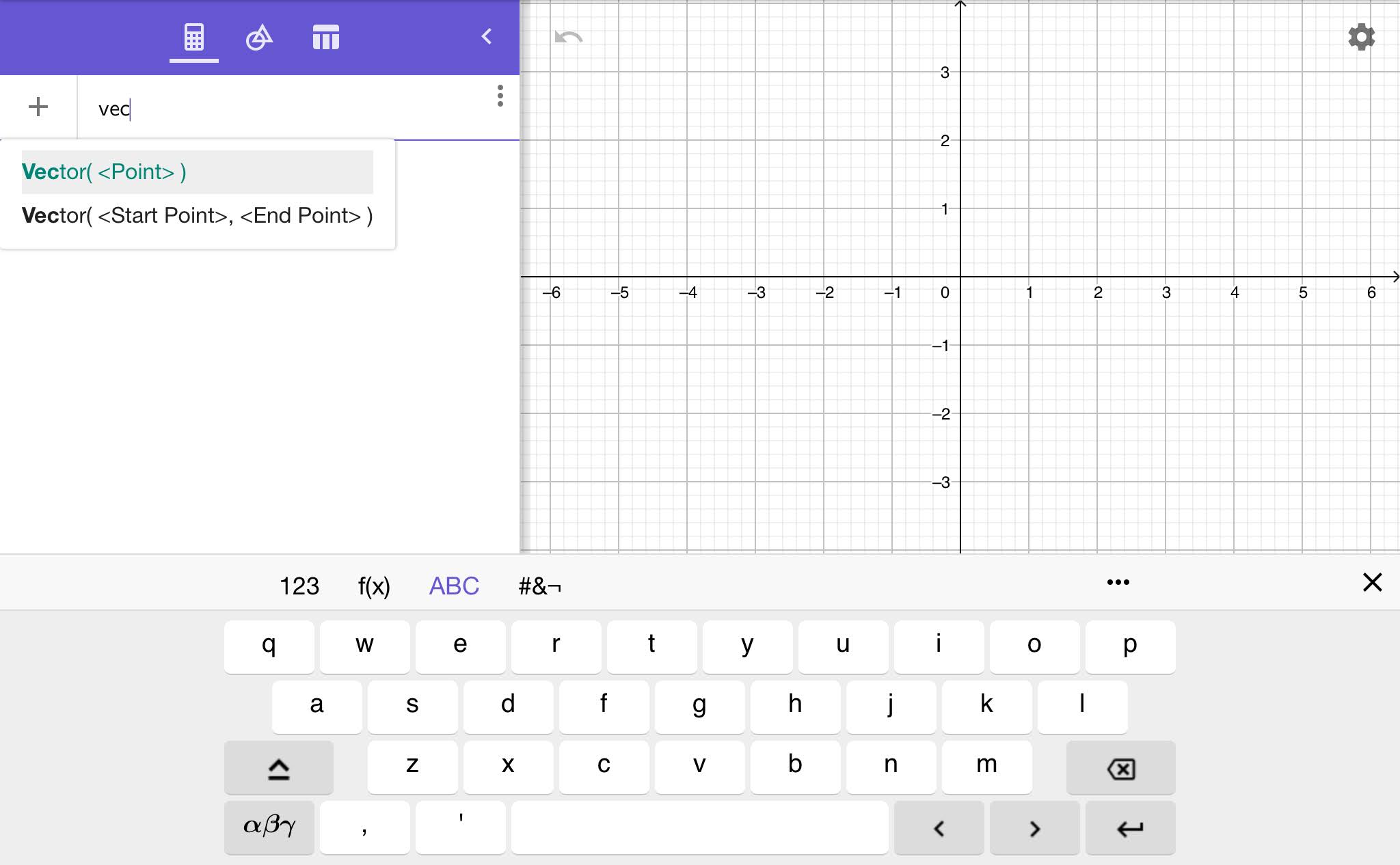
These are the commands for constructing a vector arrow. Click or tap on the command Vector(<Start Point>, <End Point>).
Start Point is where we put the coordinates of the tail or foot of the vector arrow. End Point is where we put the coordinates of the head or tip of the vector arrow.
So let’s say we want to construct a vector arrow from point (3, -1) to (2, 4). We just substitute (3, -1) in place of <Start Point> in the above command, and (2, 4) in the place of <End Point>. So the command will look like :
Vector((3, -1), (2, 4))
Once the command has been properly typed in, press enter/return to get the required vector arrow.

The calculator will automatically assign a name to it, which in our case is letter u. You can change the name anytime if you want to.
There will be many examples of vectors where you will want the tails of vector arrows to be situated at the origin. Naturally, for those vectors <Start point> will be (0,0).
But here we can also use the first command Vector(<Point>). This short command is to construct those vectors whose tails we want to be at the origin. In place of <Point> we just put the coordinates of the head of the vector.
Constructing a Vector given in component form
Say we want to construct a vector which is in component form
\(\vec{u} = 2\hat{i} - 3\hat{j}\)
2 and -3 are its scalar components. 2 is the size of the vector in the positive direction of X-axis; 3 is the size of the vector in the negative direction of Y-axis, hence the negative sign.

Let (x1, y1) be the coordinates of the tail, and (x2, y2) be the coordinates of the head of the vector. It is clear from the above picture the relation between scalar components and the coordinates of the head and the tail is
x2 - x1 = 2 ; y2 - y1 = - 3 ….(1)
It is clear that if x1, y1 are both zero, i.e. when the tail is at the origin, the coordinates of the head of the vector will be nothing but the scalar components themselves.
x2 - 0 = 2 ; y2 - 0 = -3
x2 = 2 ; y2 = -3
So if you have a vector in component form which you want to construct in geogebra, you will first need to decide where exactly you want the tail or the head of the vector arrow to be situated in the coordinate system. If you want the tail of the vector arrow to be at (2, 2), you can calculate the coordinates of the head using (1).
x2 - 2 = 2 ; y2 - 2 = -3
x2 = 4 ; y2 = -1
So the head of the vector arrow will be at (4, -1). The vector arrow can now be constructed using the command Vector((2, 2), (4, -1)).
But if you want the tail at the origin, you can simply use the command Vector(<Point>). The <Point> is substituted by the coordinates of the head which are nothing but the x and y scalar components.

(Note that u and v are the same vector, just situated at different locations. The downside of constructing vectors(or anything for that matter) in geogebra is that you can’t give the same name to two different inputs!)
We can also check the magnitude of this vector in the calculator itself. In the input row, press shift + “\” key.
You will see the cursor blinking between two vertical bars. That’s the modulus or absolute value sign. Just type in the name of the vector between the two vertical bars and press enter. The value will appear below this input; it is about 3.60 units for \(\vec{v}\) as we can see above.
Constructing Vector arrows from magnitude and direction
Now let’s say we have a vector of certain magnitude and direction that we want to draw, but we don’t know its scalar components. Say the vector is of the magnitude 5 units, and the direction is 30 degrees counterclockwise from the positive arm of X-axis. Here’s a rough sketch of how it is supposed to look.

There are a few ways to construct this vector. We can do some math beforehand to calculate the scalar components of this vector from the given info. We know how to construct a vector from its scalar components, we just saw that now.
However, there is a better, much easier way. We can avoid doing the math and simply use the rotate command in geogebra to construct this vector. Let’s see how.
Before doing anything let’s name this vector \(\vec{d}\). The magnitude of the vector arrow \(\vec{d}\) is 5 units.
So first, we draw an arrow from (0, 0) to (5, 0). This is an arrow of length 5 units but this is not quite the vector arrow we are looking for. We need to make this arrow point in the direction of \(\vec{d}\), which is 30 degrees counterclockwise from the positive X-axis. Let’s name this arrow u.

All we need to do really is rotate the arrow that we have drawn 30 degrees counterclockwise about the origin(tail of the arrow). We can do that using the command : Rotate(<Object>, <Angle>, <Point>).
The “<Object>” is the name of the object that we want to rotate, which in our case is u. The “<Angle>” is the angle by which we want to rotate the object. Make sure you mention the degree sign over the value, otherwise it will count the value in radians. Lastly, the “<Point>” is where we substitute the coordinates of the origin, the point about which we want to rotate. This point will remain fixed at the spot, and the rest of the object will rotate about it.
So the command in our case will look like, Rotate(u, 30°, (0,0,0)). Press enter/return.

You will see a new arrow with a different name, obtained from rotating the arrow u by the said angle. This new rotated arrow is the \(\vec{d}\). You can hide the original horizontal arrow u, and maybe change the name of this rotated vector arrow to ‘u’.(i have kept it ‘d’ only)

So that’s one way, an easier way, in which we can draw a vector when we know its magnitude and direction, when its direction is given in terms of the angle formed with any one of the two axes.
Comments
Post a Comment